

Time Runner
Logical Pattern Generator
Discontinued
The TimeRunner is an analog clock divider and programmable pattern generator. It utilizes a voltage controlled dual logic core to create a wide range of programmable gate patterns. The TimeRunner starts with a single clock source and divides it down into four individual channels. The output of each channel is based on a complex relationship between the clock source, a clock divider, and a chain of switchable and voltage controlled logic options. The result is a unique and extremely musical patten generator.
A Reimagining of the Timetable
The TimeRunner was not designed to be a Timetable 2. The Timetable module was built around the concept of controllable logic and the TimeRunner expands on that idea in a whole new way. The TimeRunner builds on the legacy of the Timetable by offering more complex logic routing, better control options, and more musical results.
How It Works
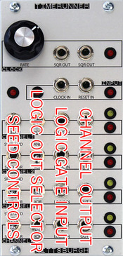
The signal path of the TimeRunner starts with an internal or external clock source. The clock is split using a divider into 4 cascading channels creating even /2, /4, /8, /16 divisions of the clock source. The output of each channel division is then split and sent to the first logic input of both an AND and XOR logic chip. The second input of the AND and XOR logic chips is referred to as the Seed. The first channel Seed is always high unless the Seed Input Jack is used. The Seed input for the remaining channels is derived from either the AND or XOR logic output of the previous channel using the Channel Seed Switch. The output of each channel is selectable between the AND and XOR logic output using the Logic Selector Switch or Logic In gate input.
Logic Selector Switch and Logic In Gate Input are at the end of the channel signal patch. Their settings affect only the output of their specific channel.
The Channel Seed Switch is at the beginning of the channel signal patch. Its setting affects the output of its specific channel and also cascades to affect the channels below. For example flipping the Channel Seed Switch on channel 2 will affect the pattern of channel 2, channel 3, and channel 4. Flipping the Channel Seed Switch on channel 3 will affect the pattern of channel 3 and channel 4. Because channel 4 is the last channel, flipping the Channel Seed Switch on channel 4 will affect the pattern of channel 4. The seed input of channel 1 works in the same way. If the Channel 1 Seed Input Jack is used, the result will affect all 4 channels.
A Simple Example
The most basic setup uses all the Channel Seed and Logic Selector switches set in the AND position. This produces a basic clock divider output. Channel 1 output divides the clock by 2. Channel 2 output divides the clock by 4. Channel 3 output divides the clock by 8. Channel 4 output divides the clock by 16.
Clocking this basic setup using an audio rate oscillator turns the TimeRunner into a 4 octave output sub-octave generator.
Flipping the Channel 1 Logic Selector switch flips the output of Channel 1 to odd beats.

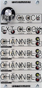
Time Runner Clock Controls:
Clock RATE - Sets the rate of the clock LFO.
SQR OUT - Square wave output of clock LFO.
SQR OUT - Square wave output of clock LFO.
INTERNAL CLOCK LED - Shows the logic state of the internal input.
SEED LOGIC LED - Shows the logic state of the seed input.
EXTERNAL CLOCK LED - Shows the logic state of the external input.
CLOCK IN - Replaces the internal LFO as the clock source.
RESET IN - Resets the internal clock divider.

Time Runner Channel 1 Controls:
SEED IN - Gate input used to set the logic state of Channel 1 Seed. If not patched, Channel 1 seed logic state is always high.
LOGIC SELECTOR SWITCH - Selects the logic sent to the output jack of Channel 1.
LOGIC IN GATE INPUT - Active when Logic Selector Switch is set to AND, the Logic In Gate Input determines the logic sent to the output of Channel 1. If the Gate input is high, logic is set to AND. if Gate input is low, logic is set to XOR.
SELECTED LOGIC LED - Yellow LED used to show the active logic state for channel 1. On represents AND, off represents XOR.

Time Runner Channel 2 Controls:
CHANNEL SEED SWITCH - Selects the logic from Channel 1 used as the seed input of Channel 2.
LOGIC SELECTOR SWITCH - Selects the logic sent to the output jack of Channel 2.
LOGIC IN GATE INPUT - Active when Logic Selector Switch is set to AND, the Logic In Gate Input determines the logic sent to the output of Channel 2. If the Gate input is high, logic is set to AND. if Gate input is low, logic is set to XOR.
SELECTED LOGIC LED - Yellow LED used to show the active logic state for channel 2. On represents AND, off represents XOR.

Time Runner Channel 3 Controls:

CHANNEL SEED SWITCH - Selects the logic from Channel 2 used as the seed input of Channel 3.
LOGIC SELECTOR SWITCH - Selects the logic sent to the output jack of Channel 3.
LOGIC IN GATE INPUT - Active when Logic Selector Switch is set to AND, the Logic In Gate Input determines the logic sent to the output of Channel 3. If the Gate input is high, logic is set to AND. if Gate input is low, logic is set to XOR.
SELECTED LOGIC LED - Yellow LED used to show the active logic state for channel 3. On represents AND, off represents XOR.
Time Runner Channel 4 Controls:
CHANNEL SEED SWITCH - Selects the logic from Channel 3 used as the seed input of Channel 4.
LOGIC SELECTOR SWITCH - Selects the logic sent to the output jack of Channel 4.
LOGIC IN GATE INPUT - Active when Logic Selector Switch is set to AND, the Logic In Gate Input determines the logic sent to the output of Channel 4. If the Gate input is high, logic is set to AND. if Gate input is low, logic is set to XOR.
SELECTED LOGIC LED - Yellow LED used to show the active logic state for channel 4. On represents AND, off represents XOR.

Time Runner Specs
Size: 12hp
Module depth with ribbon cable attached: 36.5mm
Power Usage: +12v 100mA, -12v 50mA. Does not require +5v.