
Lifeforms Double Helix Oscillator
Complex Matrix Oscillator
Sold Out
Designed to be the nucleus of a synthesizer, the Double Helix Oscillator is a modular waveform generator like no other. A set of beefy, analog oscillators paired with voltage controlled shape contouring, deep modulation, and a performance ready voltage controlled modulation matrix create a dynamic, analog waveform playground.
At the core of the Double Helix are two, wide range, precision oscillators. The primary oscillator includes a full compliment of waveforms and multiple modulation options. The Secondary oscillator offers a more focused set of waves and frequency modulation. Both oscillators reach deep into LFO range and can be used as voltage controlled modulation sources.
The contour section of the Double Helix Oscillator features a highly tuned wavefolder paired with our exclusive dynamic impulse low pass gate. The contour signal chain starts with a two channel mixer. This allows multiple waveforms or multiple oscillators to be combined before passing though the contour section. The first half of the contour section is a voltage controlled, 6 stage wavefolder used to add odd harmonics to the incoming waveform. The timbre and timbre CV controls set the density and amplitude of the folds. When processing a sine wave, the wavefolder creates a spectral change from zero harmonics to square, with an infinite harmonic series.
The second half of the contour section is a dynamic impulse low pass gate. The effect of the low pass gate is similar to pairing a low pass filter and VCA together. As the dynamics control is opened, the filter adds harmonics and the VCA increases the amplitude of the waveform. As the dynamics control is closed, the filter removes harmonics and the VCA decreases the amplitude of the waveform. This pairing mimics how sound behaves in the real world creating a more naturally tonal response. The impulse input adds the ability to strike or ping the low pass gate circuit creating a very organic, percussive sound. The decay time of the impulse input is set by the dynamics response control allowing the strike to be tuned to a specific musical context.
The modulation section includes an LFO offering simultaneous sine, square, and random waveforms. A noise source is also available for audio or modulation use.
A pair of voltage controlled routers manage all the CV inputs creating a dual, voltage controlled modulation matrix perfect for complex signal paths, experimentation, and live performance. The matrix consists of two voltage controlled amplifiers designed to control the modulation amount inputs that can be routed to any of the Double Helix CV inputs. Each of the CV inputs can be switched to channel a, bypass, or channel b and mixed with a dedicated CV input.

Double Helix Oscillator Controls

Primary Oscillator Controls
Frequency Knob - Frequency control sweeps from LFO through the full audio range.
Fine Tune Knob - Limited range frequency control.
Blade|Pulse CV Knob - Blade wave shape and Pulse width control CV input attenuator.
FM CV Knob - Frequency modulation CV input attenuator.
V/O Input Jack - 1 volt per octave pitch tracking input.
Sine Wave Output Jack - Sine wave output jack.
Saw Wave Output Jack - Saw wave output jack.
Blade Wave Output Jack - Blade wave output jack.
Sub Wave Output Jack - Sub oscillator square wave output jack.
Pulse Wave Output Jack - Pulse wave output jack.

Secondary Oscillator Controls
Frequency Knob - Frequency control sweeps from LFO through the full audio range.
Fine Tune Knob - Limited range frequency control.
FM CV Knob - Frequency modulation CV input attenuator.
V/O Input Jack - 1 volt per octave pitch tracking input.
Sine Wave Output Jack - Sine wave output jack.
Saw Wave Output Jack - Saw wave output jack.
Square Wave Output Jack - Square wave output jack.

ContouR CONTROLS
Timbre CV Knob - Timbre control CV input attenuator.
Timbre Knob - Wave folder gain control.
Dynamics Knob - Low pass gate dynamics control. Full left, no gain and no harmonics. Full right, full gain and full harmonics.
Dynamics CV Knob - Dynamics control CV input attenuator.
Dynamics Response Knob - Sets the decay time related to the impulse gate input and dynamics CV input.
In 1 Input Jack - Contour section audio signal input mixed with In 2. This jack is normalled to the Primary Oscillator Sine Wave.
In 2 Input Jack - Contour section audio signal input mixed with In 1.
Impulse Input Jack - Gate or trigger input used to strike the dynamic impulse circuit and quickly modulate the dynamics of the audio signal.
Output Jack - Contour section audio signal output jack.

Modulation CONTROLS
Frequency Knob - Frequency control sweeps through LFO range.
Square Output Jack - Square wave output jack.
Random Output Jack - Stepped Random CV output jack.
Sine Output Jack - Sine wave output jack.
Noise Output Jack - Analog noise output jack.
Voltage Controlled Routers CONTROLS
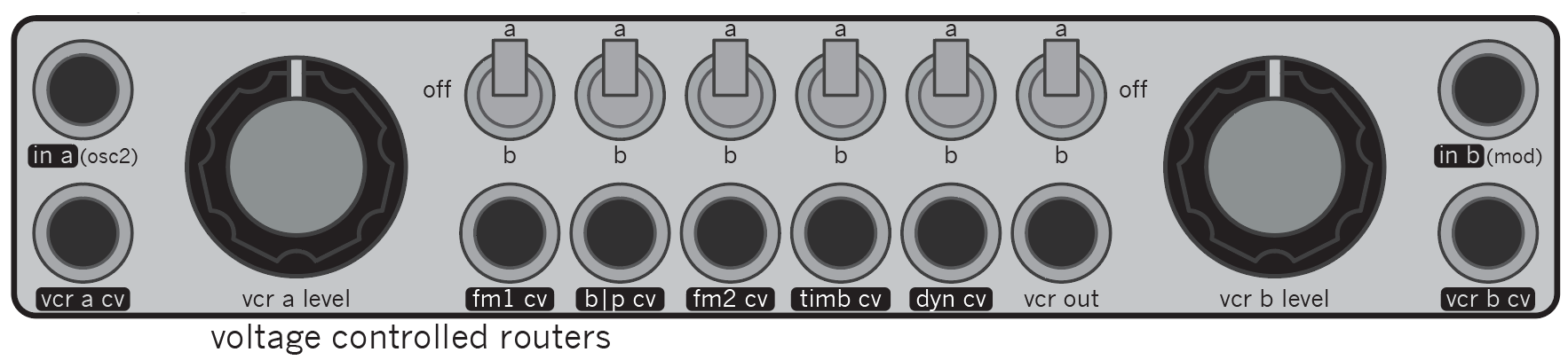
In A Input Jack - Modulation source A. This signal is sent through the voltage controlled router to any CV input switched to the A position. This jack is normaled to the oscillator 2 sine wave.
VCR A CV Input Jack - CV input used to modulate channel A modulation signal level passed through to the routing switches.
VCR A Level Knob - Sets the channel A modulation signal level passed through to the routing switches.
FM 1 CV Input Source Switch - Sets Primary Oscillator FM CV input source. Select between A (up), B (down), A and B off (center). The selected signal is mixed with the signal from the FM 1 CV Input Jack.
FM 1 CV Input Jack - Primary Oscillator FM signal input jack. The input jack is mixed with the FM 1 CV Input Source Switch.
Blade|Pulse CV Input Source Switch - Sets Primary Oscillator blade wave shape and pulse width CV input source. Select between A (up), B (down), A and B off (center). The selected signal is mixed with the signal from the Blade|Pulse CV Input Jack.
Blade|Pulse CV Input Jack - Primary Oscillator blade wave shape and pulse width signal input jack. The input jack is mixed with the Blade|Pulse CV Input Source Switch.
FM 2 CV Input Source Switch - Sets Secondary Oscillator FM CV input source. Select between A (up), B (down), A and B off (center). The selected signal is mixed with the signal from the FM 2 CV Input Jack.
FM 2 CV Input Jack - Secondary Oscillator FM signal input jack. The input jack is mixed with the FM 2 CV Input Source Switch.
Timbre CV Input Source Switch - Sets the contour section timbre CV input source. Select between A (up), B (down), A and B off (center). The selected signal is mixed with the signal from the Timbre CV Input Jack.
Timbre CV Input Jack - Contour section timbre CV input jack. The input jack is mixed with the Timbre CV Input Source Switch.
Dynamics CV Input Source Switch - Sets the contour section dynamics CV input source. Select between A (up), B (down), A and B off (center). The selected signal is mixed with the signal from the Dynamics CV Input Jack.
Dynamics CV Input Jack - Contour section dynamics CV input jack. The input jack is mixed with the Dynamics CV Input Source Switch.
VCR Output Jack Source Switch - Sets the VCR output jack source. Select between A (up), B (down), A and B off (center).
VCR Output Jack - Channel A or Channel B signal output jack. Output of modulation signal passed through to the routing swtiches.
VCR B Level Knob - Sets the channel B modulation signal level passed through to the routing switches.
In B Input Jack - Modulation source B. This signal is sent through the voltage controlled router to any CV input switched to the B position. This jack is normaled to the modulation section sine wave.
VCR B CV Input Jack - CV input used to modulate channel B modulation signal level passed through to the routing switches.
Module Specifications
Panel size: 28hp
Depth: 37mm
Power Usage: +12v 223mA, -12v 205mA. Does not require +5v. Reversed power polarity protection.